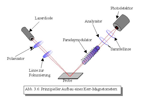
The measuring principle of the Kerr magnetometer is based on the rotation of the polarization plane of a linear-polarized light beam during reflection on a magnetic surface. In this case, a laser diode emits monochromatic light with a wavelength of l = 670 nm, which is linearly polarized by means of a polarizer and focused on the sample by a collecting lens. The reflected laser beam then passes through a Faraday modulator. This is a flint glass rod around which a coil is wound. If a current is allowed to flow through the coil, the polarization plane of the light which passes through the rod rotates in proportion to the applied current. Behind the Faraday modulator is the analyzer (a polarization filter rotated by 90 ° to the polarizer) and another lens that focuses the laser beam onto the photodetector.
Since the Kerr rotations lie only in the mrad range, the determination of the Kerr angle cannot be made by simply searching the intensity minimum by rotating the analyzer and then reading off the angle. Here the so-called lock-in measuring technique and a feedback circuit are used.
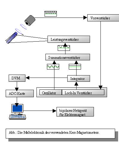
The detector signal is first amplified and passed into a lock-in amplifier. The signal at the output of the lock-in is integrated and added to the oscillator signal (reference signal of the lock-in amplifier) q ~ sinwt in an addition amplifier. Finally, another power amplifier amplifies this signal for the Faraday modulator. The rotation angle of the Faraday modulator is directly proportional to the applied current, since:
 (R=constant) and
 for a long coil.
If there is no compensation for the Kerr rotation (ie, q=¹qk), the following signal is obtained at the photodetector:
The intensity at the photodetector is now given by:

And it can be seen that for this case fractions of w in the lock-in are amplified. An output signal is thus obtained, which is then integrated in time and supplies q =. If the Kerr rotation is completely compensated (q = = qk), only components with 2w are obtained which correspond to the double reference frequency:
Jetzt gibt der Lock-In kein Signal mehr aus. Die Regelung bewirkt also, dass am Lock-In immer ein Signal von Null ausgegeben wird. Die Kerr-Drehung ist damit proportional zum Gleichspannungsanteil, den der Integrator ausgibt. Mittels einer ADC-Karte wird es digitalisiert und in einen PC eingelesen. Dieser steuert ferner ein bipolares Netzteil, mit dem man über einen Elektromagneten ein äußeres Magnetfeld an die Probe anlegen kann. Mit einem Messprogramm lassen sich dann verschiedene Feldstärken durchfahren und jeweils die Kerr-Drehung bestimmen. Somit erhält man für die untersuchte Probe spezifische Ummagnetisierungskurven.